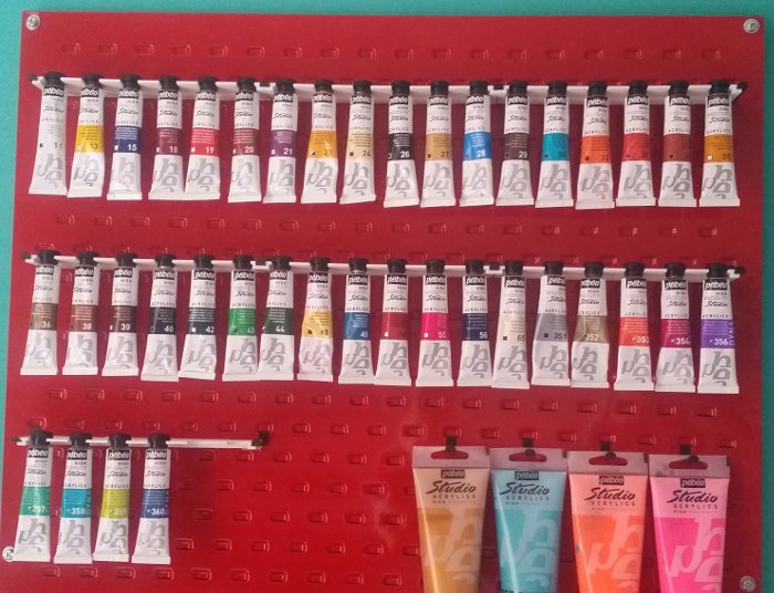
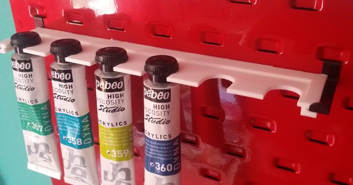
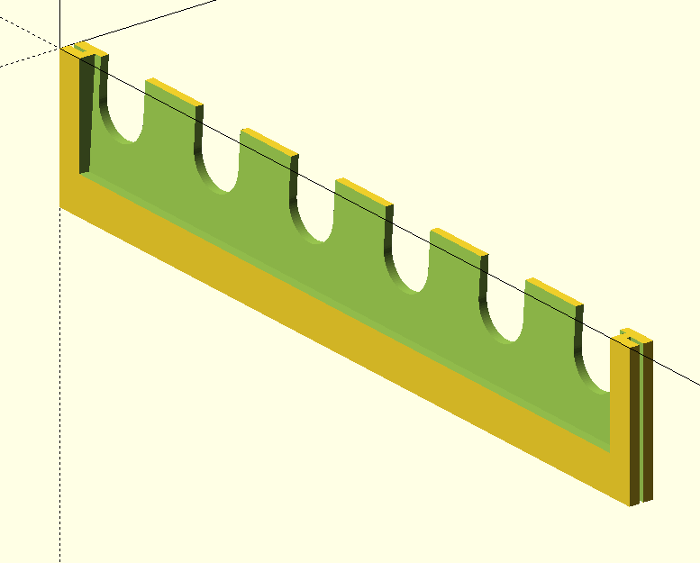
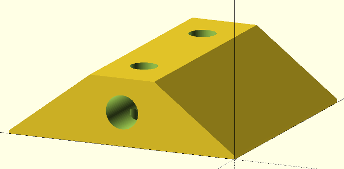
Simple 3D scad model for the Clarke CWR50 tool board - to hold small paint tubes. The shelves are angled back a little, so the tubes won't fall off. With some minor modifications I guess it would be useful for small tools etc as well.
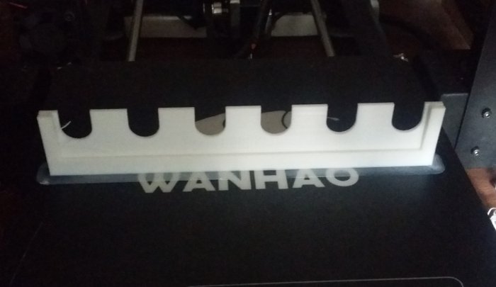
The design is fully parametric, and you can specify the number of hook perforations wide you want the shelf to be (num), the size (paint_slot_width) and spacing (paint_slot_spacing) between the centres of the paint slots. The scad code will then squeeze in as many as possible.
Ours were printed to be six hook perforations wide; that's widest I can print on my Wanhao i3, and conveniently the longest rows on the tool board were 18 wide, so I could print three per row. The paint tubes also happen to be almost the same width as the perforations too, so there's six slots.
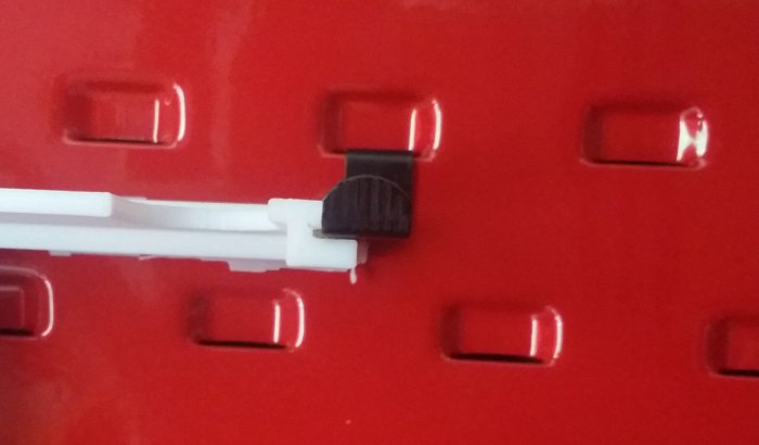
The hooks that came with the board slot into the ends of the shelves. They only go in half way though, so the hook can be shared between two adjacent shelves.
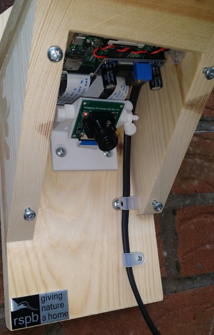
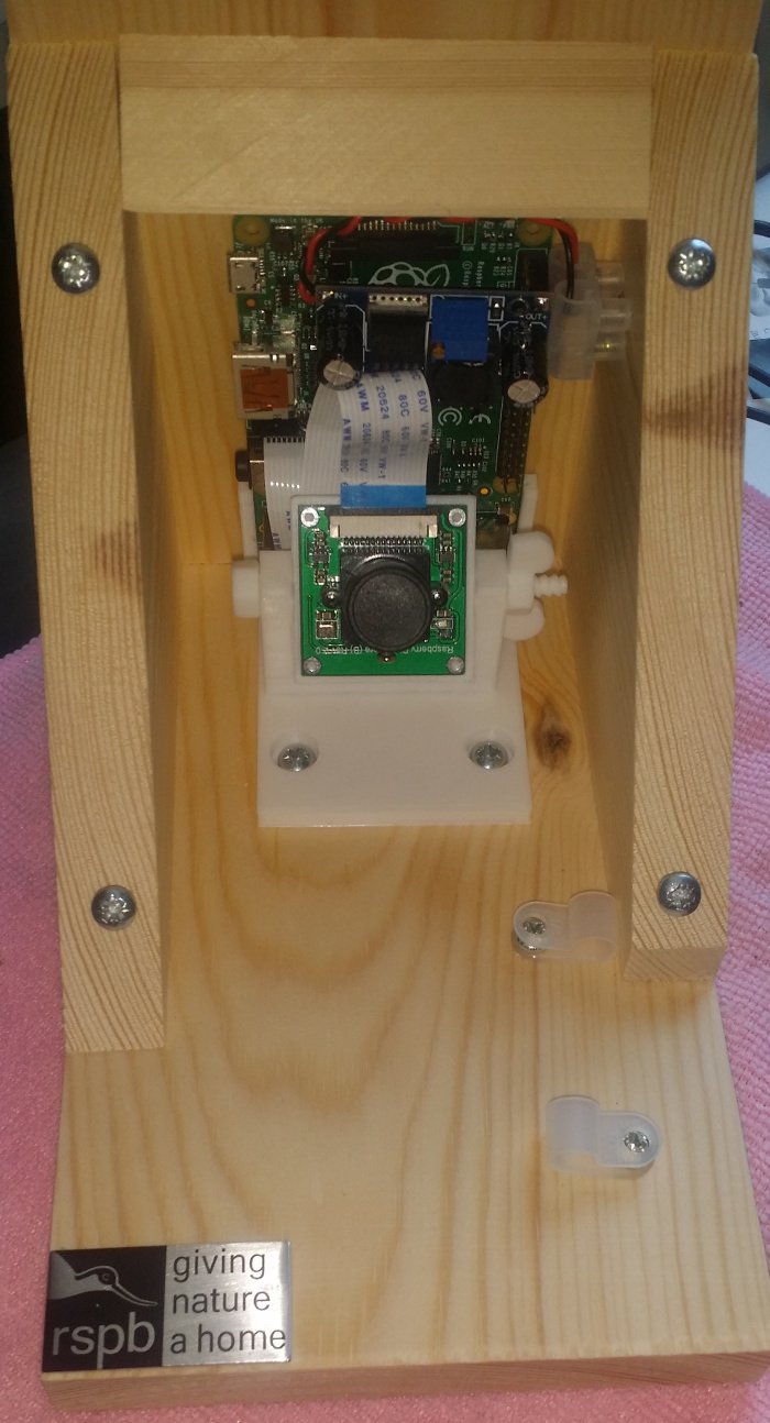
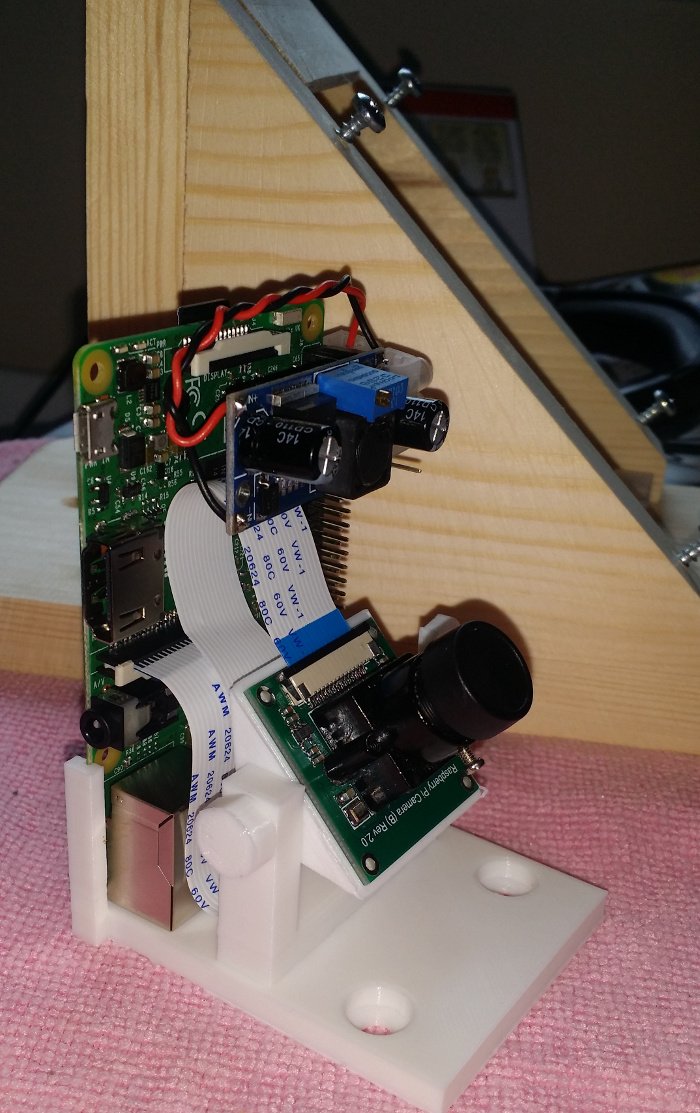
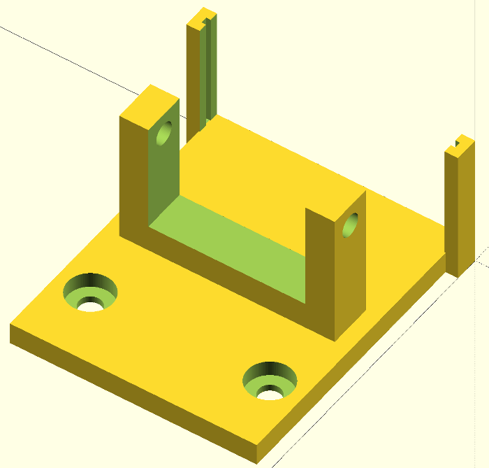
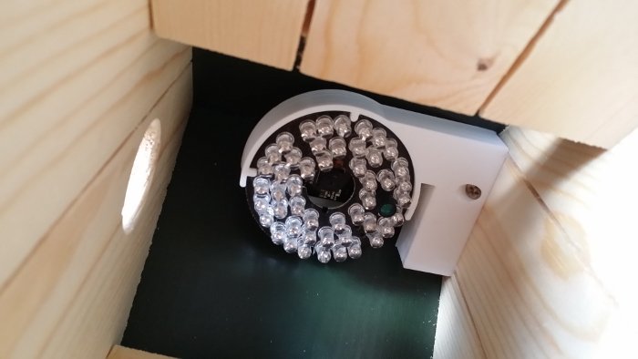
This is a drop-in raspberry pi camera mount for the RSPB's camera feeder housing. It uses the same screw and screw holes the supplied bracket uses, no modifications are required to the housing. The angle of the 'head' is adjustable, using a bolt and nut from Mike Mattala's nut job.
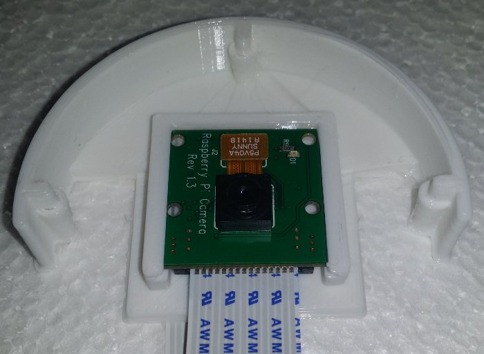
The camera board is attached using the screws used to hold the lense mount; they are simply removed, then fed through the back of the head, before going through the board and into the lense mount. The camera board I'm using
is the Waveshare OV5647, although the scad file is easily adjusted to suit most boards. (The official rpi foundation camera boards might need a pair of small nuts and bolts as they come with a small, glued down, mobile phone-type lense mount.)
The raspberry pi is slotted into two arms at the rear. Power is provided via a LM2596 based buck converter board, sat on a +5v and a ground on the 40 pin header.
Scad code for the head - adjust 'lens_screw_space' as required:
Scad code for the base - if you find that the screw holes in the feeder are off centre (mine were), you can adjust 'h_offset' to shift the bracket left or right:
Before the new bird box goes up, it needs a camera so we can monitor any nesting activity. I like to use the raspberry pi and their camera boards; they're cheap, highly customisable (a full Linux is a very useful thing) and the rpi2 is fast enough to live stream the video.
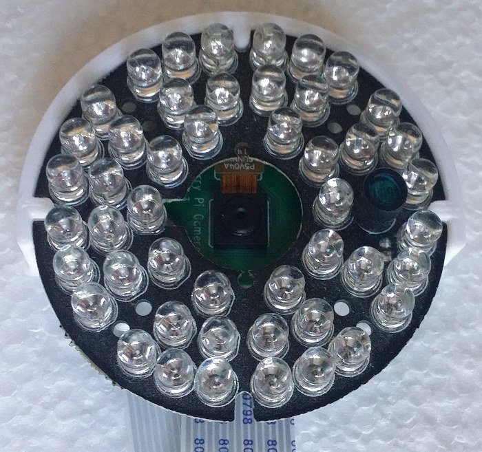
The box has only a small hole for the birds to enter through and will be pretty dark most of the time. The 'NoIR' version on the picam is used along with a very cheap, generic, doughnut-shaped, CCTV IR LED array to deal with the lack of light. (The LED array should also provide a little extra warmth for the birds - and bugs.)
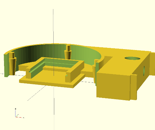
The scad code itself is split into three modules: slidein_picam(), irholder() and bracket(). Hopefully this will make things easy when I inevitably want to install another picam elsewhere. This is just the IR holder and slide in module, with just a picam installed:
The IR array is a very snug fit and is held in place by the small amount of springiness in the two left/right 'lobes' - to install mine I needed to slightly bend the lobes out, which gives it a good, solid grip.
Finally, the bracket is a simple 'L' shape, with a 45 degree counter sunk screw hole, and two short forks that fit into grooves already cut in the bird box (in the attached scad and stl I've set them to zero length as I'm imagining a flat surface is of more use to most people).
I put this openscad design together to allow me to mount some of our wildlife cameras on the same pole that the bird feeders hang from. It's been through a few iterations but this final(?) version - printed with 50% infill - is able to take the weight of a fat pigeon on the other end of the 13mm x 500mm horizontal pole. (Image of early versions at the bottom of this post.)
The code is highly parametric and should be suitable for a wide range of pole, bolt and nut (either square or hex, with captive holes) sizes. The hinge code is taken from benjaminedwardmorgan's parametric hinge. It opens to ~270 degrees; the number of hinges will be calculated automatically based on the height.
The code to generate the horizontal pole and tabs (pole_with_tabs() and pole_with_tabs_neg()) has been split into it's own modules so I can easily attach other objects to the same pole - it's my first attempt at a non-trivial openscad module and if I'm honest, usage of it feels a little clunky; I'm sure there must be a better way to deal with removing the negative image.
The available parameters are:
clamp_height - height of the clamp part
pole_diam - vertical pole diameter
screw_hole_diam - diameter of the screw holes
screw_recess_diam - diameter of the screw head/nut recess
nut_type - number of faces the nut has (4=square head, 6=hex)
horiz_pole_diam - the diameter of the horizontal pole
Expect to tweak your tolerences a little if you need things to be tightly held.
$fn = 0;

//$fs = 0.1; // HQ cylinders
//$fa = 4; // HQ spheres/hulls
render_hinges = true;

//$fs = 2; // default
//$fa = 12; // default
//render_hinges = false;

clamp_height = 30;
pole_diam = 25 +0.5;
screw_hole_diam = 4.5;
screw_recess_diam = 9;
nut_type = 4; // 4=square, 6=hex
horiz_pole_diam = 13 +0.2;

hinged_pole_clamp(
  height=clamp_height,
  hole_diam=screw_hole_diam,
  hole_recess_diam=screw_recess_diam,
  horiz_diam=horiz_pole_diam,
  nut_type=nut_type,
  pole_diam=pole_diam);


module hinged_pole_clamp(
    height,
    hole_diam,
    pole_diam,
    hole_recess_diam,
    horiz_diam,
    horiz_tab_angle=40,
    horiz_thick=3,
    nut_type=6
){
  hinge_fill_x = 23.6; //hardcoded to fit the hinge footprint
  hinge_fill_y = 20;
  hinge_fill_z = height;
  hole_r = hole_diam/2;
  pole_r = pole_diam/2;
  hole_recess_r = hole_recess_diam/2;

  hpole_r = horiz_diam/2;

  half_space = 0.5; // gap between the two halfs
  half_width = pole_diam * 1.2;
  half_depth = pole_diam * 0.6;

  flap_width = 1;
  flap_height = hole_recess_diam*1.5;

  hinge_r1 = 5;
  num_hinges = clamp_height/(hinge_r1*2) - 1;

  difference (){

    union(){


      //one half
      hull(){
        translate([
            hinge_fill_x,
            0-(half_depth-((hinge_fill_y+half_space)/2)),
            0])
            cube(size=[half_width*0.8, half_depth, hinge_fill_z]);

        translate([
            hinge_fill_x+(half_width*0.8),
            (0-(half_depth-((hinge_fill_y+half_space)/2)))+half_depth-flap_width,
            0])
            cube(size=[
              (half_width*0.2)+(hole_recess_diam*1.5),
              flap_width,
              hinge_fill_z
            ]);

      }

      difference(){
        hull(){
          translate([
            hinge_fill_x,
            0-(half_depth-((hinge_fill_y+half_space)/2)),
            0])
              cube(size=[half_width*0.8, half_depth, hinge_fill_z]);

          translate([
              hinge_fill_x,
              0-(pole_diam/2)+(horiz_thick)-(hpole_r),
              height/2])
            pole_with_tabs_neg(
              width=half_width*0.8,
              pole_r=hpole_r,
              pole_thick=horiz_thick,
              hole_diam=screw_hole_diam,
              tab=false,
              tab_angle=horiz_tab_angle);
        }

        translate([
            hinge_fill_x-(pole_diam*0.1),
            0-(pole_diam/2)+(horiz_thick)-(hpole_r),
            height/2])
          pole_with_tabs_neg(
            width=half_width*0.9,
            pole_r=hpole_r,
            pole_thick=horiz_thick,
            hole_diam=screw_hole_diam,
            tab=true,
            tab_angle=horiz_tab_angle);

      }
      //hinge fill
      translate([0, 0, 0])
          cube(size=[hinge_fill_x, hinge_fill_y+half_space, hinge_fill_z]);

      //the other half
      hull(){
        translate([
          hinge_fill_x, (0-(half_depth-((hinge_fill_y+half_space)/2)))+half_depth+half_space,
          0
        ])
          cube(size=[half_width*0.8, half_depth, hinge_fill_z]);

        translate([
          hinge_fill_x+(half_width*0.8),
          (0-(half_depth-((hinge_fill_y+half_space)/2)))+half_depth+half_space,
          0
        ])
          cube(size=[
            (half_width*0.2)+(hole_recess_diam*1.5),
            flap_width,
            hinge_fill_z
          ]);
      }

      translate([
          hinge_fill_x,
          //0-(hinge_fill_y/2)-(hinge_fill_y-half_depth)+(horiz_thick/2),
          0-(pole_diam/2)+(horiz_thick)-(hpole_r),
          height/2])
        pole_with_tabs(
          width=half_width*0.8,
          pole_r=hpole_r,
          pole_thick=horiz_thick,
          hole_diam=screw_hole_diam,
          hole_recess_diam=screw_recess_diam,
          nut_type=nut_type,
          tab_angle=horiz_tab_angle);

    }

    translate([
        hinge_fill_x+(half_width*1)+(hole_recess_diam*0.75),

        (0-(half_depth-((hinge_fill_y+half_space)/2)))+half_depth+half_space,
        height/2]){

      rotate(a=90, v=[1,0,0]){
        cylinder(h=pole_diam*1.5, r=hole_r, center=true);

        translate([0,0,0+(half_depth/2)+3])
          cylinder(h=half_depth, r=hole_recess_r, center=true, $fn=nut_type);

        translate([0,0,0-(half_depth/2)-3])
          cylinder(h=half_depth, r=hole_recess_r, center=true);
      }
    }

    //pole hole
    translate([hinge_fill_x+(half_width/2), (hinge_fill_y+half_space)/2, -(((height*1.1)-hinge_fill_z)/2)]) {
      rotate(a=90, v=[0,0,0])
        cylinder(h=(height*1.1), r=pole_r);
    }

    //hinges
    if(render_hinges)
      translate([10, (hinge_fill_y+(half_space*2))/2 ,0])
        rotate(a=(-45/2), v=[0,0,1])
          vertical_hinge_negative(theta0=45, height=(hinge_fill_z/num_hinges), n=num_hinges, r1=hinge_r1);

  }
}

/*
* tol - the smallest distance allowable between interlocking parts of your 3d printer. This gap is the
vertical (and horizontal) distance between the cones inside the hinge and is also the diameter and height of the
small support structure between hinge elements
* r1 - the outer radius of the hinge. the surface of your part should not be farther away from the center of
the hinge than this disntace.
* r2 - the furthest radius from the hinge where material is removed from the part.
* height - the height of each hinge element. The total height of the hinge is n*height. (the cut will extent
beyond this distance by height/2 on both sides. The part where you are creating the hinge should have a height
of n*height) the height must be greater than 2*r1
* n - the number of hinge elements. One hinge element is divided between the top and bottom.
* theta0 - the angle at which the hinge is printed
* theta1 - the internal angle formed when the hinge is turned to its limit in one direction (the x- part of the
hinge_test_1 example when rotated clockwise as viewed from above)
* theta2 - the internal angle formed when the hinge is turned to its limit in the opposite direction
*/
module vertical_hinge_negative(tol=0.5,r1=5,r2=15,height=15,n=2,theta0=180,theta1=45,theta2=45) {

    arm_width=2*r1;
    union() {
        for(i=[0:n])
            translate([0,0,(i-0.5)*height])
                difference() {

                    //cone between hinges and cuts around the hinge
                    rotate_extrude()
                        polygon([[r1,0],[r1,height],[tol/2,height-r1+tol/2],
                                [tol/2,height-r1+1.5*tol],[r1,height+tol],
                                [r2,height+tol],[r2,0]]);


                    //exclude a rectangular shape for the arm the connects the hinge to the body
                    rotate((i%2)*theta0)
                        difference() {
                            translate([0,-arm_width/2,-height])
                                cube(size=[r2*2,arm_width,height*2]);

                            translate([0,0,height-r1])
                                cylinder(r1=0,r2=height,h=height);
                        }

                    //exclude a triangular shape that limits the motion of the arms on the side of the hinge
                    for(i=[0,1])
                        mirror([0,i,0])
                            rotate(-i*theta0)
                                translate([0,0,-tol])
                                    linear_extrude(height=height+3*tol)
                                        intersection() {
                                            circle(r=2*r2);

                                            rotate(theta0+180+theta2)
                                                translate([0,r2*3+arm_width/2+tol])
                                                    square(size=[r2*6,r2*6],center=true);

                                            rotate(theta0-theta1)
                                                translate([0,r2*3+arm_width/2+tol])
                                                    square(size=[r2*6,r2*6],center=true);

                                            rotate(theta0)
                                                translate([r2*3,0])
                                                    square(size=[r2*6,r2*6],center=true);
                                        }
            }
       }
}


//*********************************************************

module pole_with_tabs_neg(width, pole_r, pole_thick, hole_diam, tab=false, tab_angle=0, gap=1){
  rotate(a=90, v=[0,1,0]){
    cylinder(h=width, r=pole_r+pole_thick);
  }

  if(tab==true){
    // screw hole in tab
    rotate(a=tab_angle, v=[1,0,0])
      translate([width/2,
                 0,
                 pole_r+(pole_thick)+hole_diam ]) {
        // tab gap
        cube([width*1.1, gap, (hole_diam*2)+(pole_thick*3)], center=true);
      }
  }
}

module pole_with_tabs(width, pole_r, pole_thick, hole_diam, hole_recess_diam, nut_type=6, tab_angle=0, gap=1){
  hole_r = hole_diam/2;
  difference(){
    union(){
      rotate(a=90, v=[0,1,0]){
        cylinder(h=width, r=(pole_r+pole_thick)*1.01);
      }

      // tab block
      hull(){
        rotate(a=90, v=[0,1,0]){
          cylinder(h=width, r=(pole_r+pole_thick)*1.01);
        }
        rotate(a=tab_angle, v=[1,0,0])
          translate([width/2, 0, ((hole_recess_diam)+(pole_thick*2)+pole_r)/2]){
            cube([
              hole_recess_diam,
              (pole_thick*2)+gap,
              (hole_recess_diam)+(pole_thick*2)+pole_r],
              center=true);
          }
        }
    }

    // pole hole
    translate([0-(width*0.5), 0, 0])
      rotate(a=90, v=[0,1,0]){
        cylinder(h=width*2.0, r=pole_r);
      }

    // screw hole in tab
    rotate(a=tab_angle, v=[1,0,0])
      translate([width/2,
                 0,
                 pole_r+(pole_thick)+(hole_recess_diam/2) ]) {

        // screw hole
        rotate(a=90, v=[1,0,0]){
          cylinder(h=pole_r*3, r=hole_r, center=true);

          //nut/screw recesses
          translate([0, 0, 0+(pole_r/2)+(pole_thick+gap)]){
            cylinder(h=pole_r, r=hole_recess_diam/2, center=true);
          }
          translate([0, 0, 0-(pole_r/2)-(pole_thick+gap)]){
            cylinder(h=pole_r, r=hole_recess_diam/2, center=true, $fn=nut_type);
          }
        }

        // tab gap
        cube([width*1.1, gap, (hole_recess_diam*2)+(pole_thick*3)], center=true);
      }
  }

}
Early versions; too flimsy, couldn't take the weight of the fat pigeons:
Fat pidgeons kept disturbing my carefully positioned birdcams. To disuade them from landing on the most sensitive places I've knocked up some parametric clip on spikes.
The available knobs to twiddle are:
pole_dia - diameter of the pole
pole_thick - thickness around the pole (3mm)
pole_h - height of the pole clip (10mm)
spike_l - spike length (60mm)
spike_h - spike height (2mm)
spike_w - spike width (3mm)
The clip part is pretty much the same as my cable clip.
For another project I needed to run various cables to some pole mounted kit. The poles are two different diameters, so I put together this parametric design so I would only need one model.
The available knobs to twiddle are:
pole_dia - diameter of the pole
pole_thick - thickness around the pole (3mm)
pole_h - height of the print (5mm)
clip_thick - thickness of the cable clip part (2mm)
clip_depth - depth of the clip space
Hopefully only the pole diameter needs to be changed; 3mm around the pole seems to hold firmly and 2mm for the clip gives enough flexibility to easily pop cables in and out. If the cables are fat then the clip depth can be increased as required.
A couple of months ago I bought a Reprap 3D printer, and to make space for it in the lab I also brought a bunch of keyhole shelving units. For a while I'd been thinking it would be nice to print a simple hook that would fit the keyholes and while browsing thingiverse I found Timmytool's parametric hook. Now I had somewhere to hang my favourite pair of pliers, but the hook was no good for my favourite screwdriver :)
The script I put together is based on Timmytool's scad file on thingiverse (and still mentions the 'hook' - I was being lazy and haven't unpicked all the original wedge logic) and configuring the keyhole dimensions is still the same:
key_big - diameter of the large round part of the key hole
key_small - diameter of the small offshoot from the main key cylinder
key_spacing - distance from one key hole to the same point in the next key hole
key_thickness - thickness of the material the key holes are cut from
Additionally, to configure the shelf and holes:
shelf_width - width of the 'shelf', centred around the keyhole
shelf_hole_radius - radius of the holes
num_holes - the number of holes
The script will attempt to calculate the depth of the shelf and an even spacing between the holes.
shelf_width=100, shelf_hole_radius=6, num_holes=4
shelf_width=100, shelf_hole_radius=3, num_holes=8
//width of the shelf
shelf_width = 100;
//radius of the holes
shelf_hole_radius = 3;
//number of holes
num_holes = 8;


//diameter of the large round part of the key hole,make smaller then real (for clearances)
key_big = 11;
//diameter of the small offshoot from the main key cylinder,make smaller then real (for clearances)
key_small = 6;

//distance from one key hole to the same point in the next key hole, make slightly bigger then real (for clearances)
key_spacing = 39;
//thickness of the material the key holes are kut out of, make slightly bigger then real (for clearances)
key_thickness = 1.75;

//thickness of lugs and support bar
support_thickness = 4;

hook = 10;

//calculated
spacer = ((shelf_width - (shelf_hole_radius * 2 * num_holes)) / num_holes) / 2;
poke = (shelf_hole_radius*2)+hook;
hookStart = support_thickness*2+key_thickness;
angle = atan ( hook / poke);
hype = poke + hook;
KBR = key_big/2;
KSR = key_small/2;

module wedge()  {
	translate([0,-key_small,0]) difference() {
		cube([poke,key_small,hook]);
		rotate(a=[0,-angle,0])translate([0,-1,0])cube([hype,key_small+2,hook]);
	}
}

module betterjoints() {
	intersection(){
		translate([0,-KSR,0])cube([key_spacing,key_small,support_thickness*2+key_thickness]);
		cylinder(h= support_thickness*2+key_thickness ,r1 = KBR , r2 = KBR,$fn=36);
	}
}

translate([-KBR- key_spacing/2,-KBR,0]) {		//to centre item on the build platform

  difference() {
    //shelf
    translate([KBR, KBR - (shelf_width/2), hookStart]) {
	    cube([hook/2, shelf_width, poke]);
    }

    //holes
    for ( i = [1 : num_holes ] ) {
      translate([
	      (KBR/2)-(hook/2),
	      KBR - (shelf_width/2) + (shelf_hole_radius + spacer)*(i *2-1),
	      hype-(poke/2)+(key_small/2)]) {

	      rotate([0, 90, 0]) {
		      #cylinder(h = hook*2, r = shelf_hole_radius);
	      }
      }
    }
  }


  translate([KBR,KBR - KSR,hookStart]) {		//support bar making and wedge
    translate([poke,0,0])rotate(a=[0,0,180]) wedge();
    translate([0,0,-support_thickness]) cube([key_spacing,key_small,support_thickness]);
  }

  translate([KBR,KBR,0]) {								//post 1
	  cylinder(h= hookStart + poke, r1 = KSR ,r2 = KSR,$fn=36);
	  cylinder(h= support_thickness ,r1 = KBR , r2 = KBR,$fn=36);
	  betterjoints();
	  translate([key_spacing,0,0]){						//post 2
		  cylinder(h= hookStart, r1 = KSR ,r2 = KSR,$fn=36);
		  cylinder(h= support_thickness ,r1 = KBR , r2 = KBR,$fn=36);
		  betterjoints();
		  }
	  }
}