battletanks reverse engineering
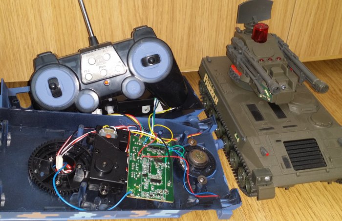
We've been watching the repeats of the old robot wars for a while now and with the start of the new series we thought we'd quite like to have some small scale wars at home. While I'd like to build a pair of robots from scratch, this would likely take more time than I have available. So I took my fingers to amazon to look for a couple of RC vehicles that had more than just the driving controls, so the extra functions could be utilised to drive weapons/flippers etc.
After a bit of searching I found a double pack of "battle tanks". They have the expected forwards, backwards and rotate left/right drive controls, but also have rotating turrets and some other buttons (fire, fx1, fx2, demo and on/off). Out-of-the-box the game is that each tank has three lives and has to shoot the other - they have a IR LED and receiver mounted on the turret (you can see them on the Panzer). The tanks also produce a bunch of sound effects to accompany the game.
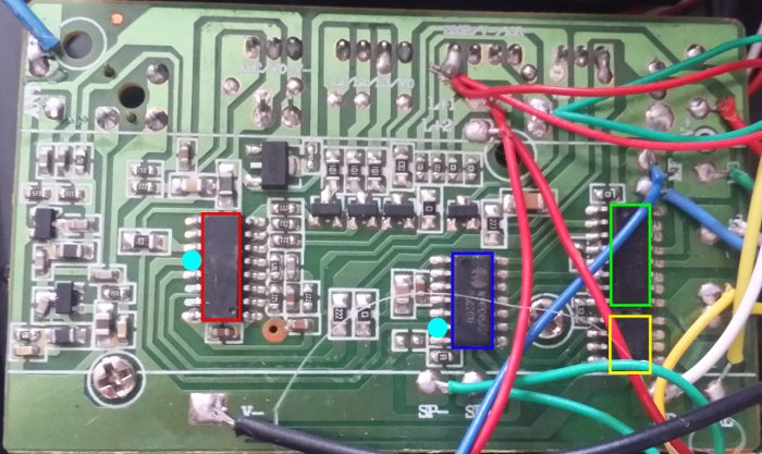
Taking a look at the board inside one of the tanks, you can see that it's primarily made up of four ICs: the first one implements the radio receiver and the majority of the game (red); it's connected directly to the IR and RF electronics, as well as the three 'lives' LEDs on top of the turret. The red chip is connected to the second IC (blue) by a single data line (the two cyan pins on the red/blue chips). The blue chip generates both the sound effects (the speaker is directly connected to it - green wires: SP-/SP+) and the signals required to drive the two H-bridge ICs that control the tracks (green) and turret motors (yellow).
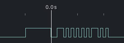
The data line is an one-way path from the red IC to the blue IC. Data is sent nine bits at a time, with a ~970us high/~240us low indicating the start (the zero line in the image above is at the high/low transition). The bits themselves are encoded as a either ~100us or ~240us pulses, with a ~100us gap between them. Assuming 100us is one and 240us is zero, the above example decodes as "100000100".
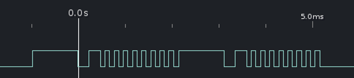
Some button presses translate to multiple bytes (above is the demo button). The red IC also tracks a certain amount of state: the fx2 button will cycle through three different set of bytes on each button press. Here's most of the mappings:
shoulderR   110000000
shoulderL   101000000

left        100010000
right       100001000
forward     100000100
backwards   100000010

demo        100000000 100000000
shoot+sound 100000000 000000010
fx1         000001100 100000000
byebye      000010010
on          000000100
off         000010010 100000000
fx2,1       000011010 100000000
fx2,2       000000110 100000000 000000110
fx2,3       000000010 100000000
From here it should be possible to remove the blue chip and then patch in a microcontroller. It should be able to detect the controls and then either drive the existing H-bridges, or additional servos, sensors etc. Removing the IR receiver and tying it's line should effectively disable the built-in game.
That's the plan anyway...